


Basic knowledge of drills (2) Elements that make up a drill
Dec. 7. 2021
In this article, We would like to explain the elements that make up a drill in an easy- understandable way, including the definition in JIS.
Elements that make up a drill
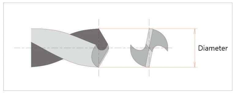
Diameter
Dimensions of the outer diameter of the blade tip. (From JIS B 0171: 2014)
When measuring with a caliper, be sure to measure at the outermost position of the tip. In the case of general drills, the diameter is slightly smaller near the shank than at the tip due to the back taper.
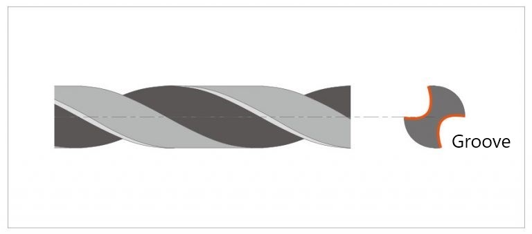
Groove
A dented area for chip evacuation between adjacent cutting edges and heels. (From JIS B 0171: 2014)
This is the spiral groove of a drill. This groove constitutes the rake side of the cutting edge and serves to eject chips. If the twist of the helix of this groove is increased, the rake angle becomes smaller (acute angle), but the chip evacuation becomes worse. On the other hand, if the twist is small, the rake angle becomes large (obtuse angle), but the chip evacuation is improved.
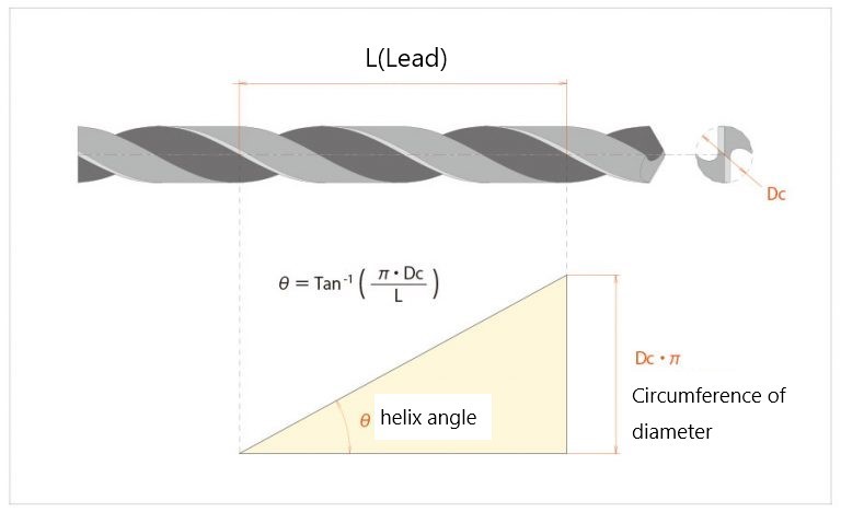
Lead
The distance traveled in the axial direction when circling around an axis along a leading edge. (From JIS B 0171: 2014)
To put it simply, it is the distance in the axial direction when making a full circle along the groove.
Helix angle
This is the angle that represents the degree of helix twist in the groove. It is the θ angle of the right triangle formed by the lead and diameter circumference shown above.
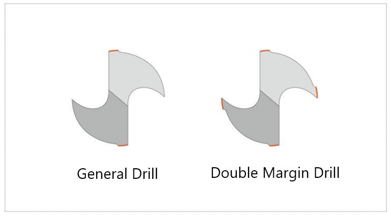
Margin
The part of the cylindrical surface on the land that has not been chamfered. (From JIS B 0171: 2014)
This is the part that serves as a guide around the periphery when drilling a hole with a drill. Normally, there is one margin per cutting edge (attached to the outermost edge of the cutting edge), but double margin drills are also available to improve hole accuracy.
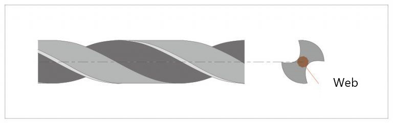
Web
The part formed by the groove bottom. (From JIS B 0171: 2014)
In the case of a normal drill, there are two grooves (for the number of blades), and the grooves are formed by cutting a small portion of the center of the shaft. The remaining portion is called the web, and the web at the tip is called the “core thickness”.
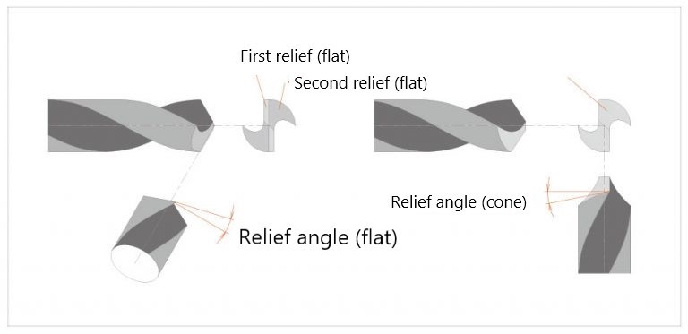
Relief surface
A surface that is released to avoid unnecessary wear with the workpiece surface during the cutting process. There are two types of escape surface shapes: conical and flat. (From JIS B 0171: 2014)
When the tip of a drill is viewed from above, it is the surface that constitutes the cutting edge and is lowered (escaped) behind the direction of rotation. Since the drill moves forward in the axial direction while rotating, if the back side of the cutting edge is higher than the cutting edge, it will contact the work material and the cutting edge will not be able to cut. A conical flank consists of a single curved surface, while a flat flank generally consists of two surfaces: the “first relief” on the cutting-edge side of the centerline and the “third relief” behind the centerline.
Relief angle
This is the angle of the relief surface. The definition is slightly different for cone relief and flat relief.
In the case of cone relief, it is the angle at which the outermost circumference escapes backward in the axial direction, while in the case of flat clearance, it is the angle at which the circumference escapes backward from the standard, which is a tip angle down from the axial direction. (See the figure.)
The tighter (larger) the clearance angle is, the sharper the cutting edge becomes, and the cutting resistance is reduced, but the cutting edge becomes thinner and more brittle. On the other hand, if the relief angle is made weaker (smaller), the rigidity of the cutting edge is improved, but the back of the flank will contact the work material unless the feed rate is reduced.
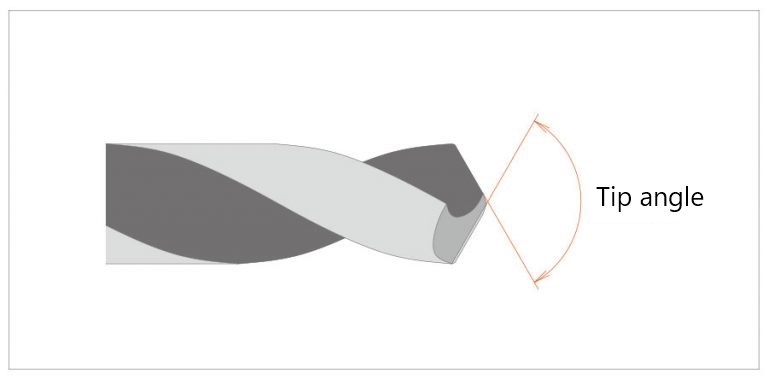
Tip Angle
The angle when the cutting edge is projected parallel to the surface parallel to the axis of the drill. (From JIS B 0171: 2014)
Please refer to the figure. Basically, it is the angle seen from the side when the cutting edge is parallel, but for center drills and other drills where the angle on the work material side after machining is important, it is the angle in the rotational projection (approximation). The tip angle affects cutting resistance and depth of cut, and the optimum angle varies depending on the material of the work material, drill material, etc.
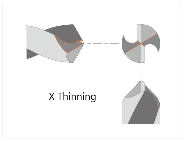
Thinning
A portion of a web tip that is made particularly thin. It is used to reduce cutting resistance. (From JIS B 0171: 2014)
A drill cannot have a cutting edge in the web part due to its structure. In actual cutting, this part crushes the work material it contacts with, which causes a large cutting resistance. Therefore, a cut is made here to simulate a cutting edge and reduce the cutting resistance. Various shapes of thinning are available depending on the application and conditions.
In this article, we have explained the main elements that make up a drill. In the next article, we will explain these elements in more detail.